

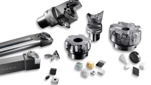
Illustrated guide for turning and milling
Mild / alloy steel
| Stainless steel |
Hardened die / tool steel | Extra focus on milling inserts
Who this is for: a tool room running CNC turning centres and VMCs, and anyone who wants to understand why a tool or insert is chosen, not just which one. Everything is in plain language with drawings and tables you can print.
How to use it: Part 1 gives the selection method on one page. Parts 2 to 4 are the
basics of cutting and insert codes. Part 5 is turning. Part 6 is the detailed
milling section. Parts 7 to 9 cover formulas, reading tool wear and shop tips.
The last page is a cheat sheet to pin near the machine.
Please note: Speeds, feeds and depths are typical
starting ranges, not final data. Every insert maker publishes exact values
for each grade and geometry. Start in the middle of the range, check tool wear,
then adjust.
Part 1. The selection method on one page
Choose in the same order every time. The first three steps describe the job, the next
three choose the tool, and the last three decide how to run it.
Skipping the early steps is how people end up with chipped inserts and poor
finish.

Figure 1. Nine-step method for selecting
a cutting tool and insert.
1.
Work material and hardness. Mild steel, alloy
steel, stainless, pre-hardened (28 to 40 HRC) or fully hardened (45 to 62 HRC)?
This sets the ISO group and the tool material.
2.
Operation. Roughing, semi-finishing or
finishing? External, internal, facing, profiling, grooving? Slotting, shoulder,
face, contour or pocket?
3.
Stability. Machine power and rigidity, work
holding, tool overhang, thin walls, interrupted cut (keyways, cross holes,
scale). Poor stability means a tougher grade, a positive insert and a lower
depth of cut.
4.
Tool body. Holder style and entering angle for
turning. Cutter type (face mill, shoulder mill, high-feed, round insert, ball
nose, solid end mill) for milling.
5.
Insert shape and size. The strongest shape that
can still reach the part geometry. Depth of cut should not exceed about
two-thirds of the cutting-edge length.
6.
Nose radius and geometry (chip breaker).
Finishing, medium or roughing geometry; positive or negative insert.
7. Grade and coating. Tougher for rough or interrupted work, harder for continuous finishing.
8. Speed, feed and depth of cut from the maker’s recommendation, then fine-tune.
9. Run, look at the wear, record it. The worn edge tells you what to change (Part 8).
Part 2. Cutting basics you need before choosing anything
2.1 What happens at the cutting edge
A cutting tool is a wedge. It shears a thin layer of metal off the work and turns it into a
chip. Three things then happen at the edge: the metal is sheared, the
chip rubs over the top of the insert, and the energy turns into heat.
At the right speed most of that heat leaves with the chip. At the wrong speed
it stays in the insert and the edge wears or deforms quickly.
That is why every selection decision comes back to three questions: how strong is the edge (to survive the force), how hard is it (to survive the rubbing), and how well
can it resist heat (to survive the speed).
2.2 The three cutting data: speed, feed and depth
|
Setting |
What |
Effect |
Effect |
|
Cutting |
How |
Biggest |
Raises |
|
Feed |
How |
Medium |
Raises |
|
Depth |
How |
Smallest |
Raises |
Shop tip: To get more metal removed without
ruining tool life, increase depth of cut first, then feed, and keep the
speed moderate. Speed is the expensive one.
2.3 Positive and negative inserts (the wedge)
The angle of the wedge decides how strong and how free-cutting the insert is. A negative insert has a blunt, strong wedge (about 90°) and cuts with higher force. A positive insert has a slimmer wedge (about 70°), cuts with less force and heat, but is
not as strong.

Figure 2. Negative versus positive
insert: the wedge angle decides strength against free cutting.
2.4 Hard versus tough: the one trade-off behind every grade
Carbide inserts are tungsten carbide grains (very hard) held by cobalt (the glue). More cobalt and coarser grains make the grade tougher. Less cobalt and finer grains
make it harder. You cannot have both at the maximum.
•
A hard grade resists wear, stays sharp and gives
a good finish at high speed. But it can chip if the cut is rough or
interrupted.
•
A tough grade survives shock and heavy cuts, but
wears faster and cannot run as fast.
Think of a glass knife and a soft iron knife. The glass knife is razor-sharp but snaps if
you twist it. The iron knife never snaps but goes blunt quickly. Selecting a
grade means choosing the right point between the two. Rough or interrupted
cut: lean tough. Smooth, continuous finishing: lean hard.

Figure 3. The ISO scale: low numbers are
hard (finishing), high numbers are tough (roughing).
Old book note: Older books number grades the other way: C1 or C5 meant roughing and C4 or C8 meant fine finishing. The ISO scale runs the opposite way (P01 finishing, P40 roughing), so always check which system a chart uses.
Part 3. Reading insert codes (ISO 1832)
Every insert box carries a code. It looks cryptic, but it is just seven fields in a fixed
order. The modern metric code CNMG 120408 is the same insert that older
inch charts call CNMG 432.

Figure 4. Decoding CNMG 120408 field by
field.
3.1 Inch to metric conversion
|
What |
Old |
ISO |
|
Size |
2 3 4 5 6 8 |
06 09 12 16 19 25 |
|
Thickness |
2 3 4 5 |
03 04 06 07 |
|
Nose |
1 2 3 4 |
04 08 12 16 |
3.2 The most useful letters
|
Position |
Common |
|
Shape |
C |
|
Clearance |
N |
|
Tolerance |
G |
|
Type |
A |
Many catalogue codes continue after the seven fields, for example CNMG 120408-PM. The extra letters are the maker’s own chip breaker name, so they differ between
brands. There can also be a letter for edge preparation (F = sharp, E = honed,
T = chamfered, S = chamfered and honed) and for hand of cut (R, L or N).
3.3 The tool holder code
A holder such as PCLNR 2525 M12 reads the same way: P = clamping system (lever
through the insert hole), C = insert shape (80° diamond), L =
holder style (95° entering angle), N = insert clearance (0°, negative), R
= right hand, 2525 = shank 25 × 25 mm, M = length 150 mm, 12
= cutting edge length 12 mm. This holder takes CNMG 1204xx inserts.
Part 4. Insert shapes, grades and coatings
4.1 Insert shapes
Shape decides two things: how strong the cutting corner is, and how many edges
you get per insert. The bigger the corner angle, the stronger the insert. The
smaller the angle, the better it reaches into profiles.

Figure 5. Common insert shapes, from
strongest (round) to best reach (35° diamond).
|
Shape |
Best |
Points |
|
C CNMG 120408 CCMT |
General |
The |
|
D DNMG 150608 DCMT |
Profiling |
Weaker |
|
V VNMG 160408 VBMT |
Fine |
Weakest |
|
T TNMG 160408 TCMT |
General |
Weaker |
|
W WNMG 080408 |
All-rounder |
Same |
|
S SNMG 120408 |
Heavy |
No |
|
R RNMG 120400 |
Heavy |
Higher |
Wiper
inserts (a flat blade-like edge on the nose) allow about double the feed
for the same surface finish, or a much better finish at the same feed. They
are very useful for finishing steel and stainless, but need a stable setup. Threading,
grooving and parting use their own special inserts, and the same selection
steps apply.
4.2 The ISO colour groups
Modern selection starts with the work material group, marked by a letter and a
colour on the insert box.

Figure 6. The six ISO work-material groups and examples from your shop.
Within each group a number from 01 to 50 shows where the grade sits between hard and tough (Figure 3). Most makers publish a bar chart (“application range”) per grade, and you choose the grade whose bar covers your operation.
4.3 What is inside a modern insert
• Substrate (the body): tungsten carbide with cobalt binder, usually 6 to 12% cobalt. More cobalt gives toughness. Finer grains give a sharper, stronger edge.
• Coating: a very thin ceramic-like layer (a few microns) that resists heat and wear, so you can run faster.
|
|
CVD coating |
PVD coating |
|
Typical layers |
TiCN base, Al2O3 (aluminium oxide) middle, TiN top |
TiAlN, AlTiN, AlCrN (single or multilayer) |
|
Thickness |
Thicker (about 5 to 20 microns) |
Thinner (about 2 to 5 microns) |
|
Edge |
Slightly rounded |
Can hold a sharper edge |
|
Toughness in interrupted cut |
Lower |
Higher |
|
Heat resistance |
Excellent. Good for fast continuous cutting in steel. |
Very good. AlTiN and AlCrN excel in hard materials. |
|
Best for |
Steel turning, roughing to medium finishing, continuous cut |
Stainless, small finishing, interrupted cut, milling, hardened steel, threading, grooving |
4.4 Other tool materials worth knowing
|
Material |
What it is good for |
Remember |
|
Cermet (TiC / TiN based) |
High-speed finishing of steel and stainless with very good surface finish. |
Does not like heavy or interrupted cuts. |
|
Ceramic |
Cast iron at high speed, hardened steel (mixed ceramic), heat-resistant alloys. |
Brittle. Usually run dry or with very steady coolant. |
|
CBN (cubic boron nitride) |
Hard turning of hardened steel above about 45 HRC. Often replaces grinding. |
Costly, but cost per part is often lower. Needs a rigid machine, usually dry. |
|
PCD (polycrystalline diamond) |
Aluminium, copper and non-metals. |
Never use on steel. |
|
HSS / cobalt HSS |
Drills, taps, reamers, form tools and low-speed work. |
Still essential in a tool room. |
